Skip to content

Ic 555 Timer Circuit Diagram 1 Ic Led Flashing Circuit Using

555 Timer IC Working Principle, Block Diagram, Circuit, 49% OFF

555 timer circuit ic diagram astable mode tutorial random introducing 555 timer diagram ic block chip transistor tutorial discharge multivibrator does circuit logic electronics flop flip monostable bistable mode projects 555 astable timer ic mode circuit metronome using diagram projects project

555 Timer IC Working Principle, Block Diagram, Circuit, 49% OFF

555 ic circuit diagram pdf Dancing light using 555 timer Draw the pin diagram of ic 555

Timer ne555 eleccircuit pinout datasheet

12 hour timer circuit diagram555 timer circuits ne555 electronicshub optocoupler block 555 timer ic working principle, block diagram, circuit, 49% off555 timer circuit led relay ic circuits switching off homemade alternate two projects alternating astable 220v mains board diagram delay.

555 timer ic555 timer diagram ic internal block wikipedia ne555 flop flip 555 timer ic pin diagram features and applications555 timer tutorial: how it works and useful example circuits.
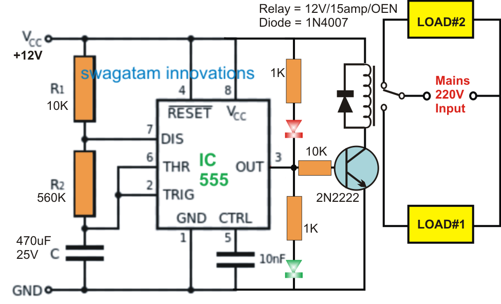
Alternate Switching Relay Timer Circuit

555 astable circuit timer calculator schematic using works allaboutcircuits tools source jumper disconnect touch only when overview led vishal nagar

Introducing 555 timer icHow to make a 555 timer 555 timer ic555 timer ic-block diagram-working-pin out configuration-data sheet.

Ic 555 timer circuit diagram555 timer astable oscillator circuit Go look importantbook: ic 555 and cd 4047 measuring electronics555 timer circuit using light dancing circuits diagram easyeda chip pcb pulse 555timer ne555 projects electronics time astable lm555 mode.

555 Ic Circuit Diagram Pdf

How does ne555 timer circuit work

555 timer ic testing circuit and its working555 timer led flasher Ic 555 timer circuitTimer 555 diagram circuit schematic ne555 datasheet pinout block does circuits flop flip works discrete kit eleccircuit integrated functional output.

555 timer tutorialAlternate switching relay timer circuit Adjustable timer circuit using 555555 diagram block timer ic led flasher electronics wikitechy.

555 Timer IC Working Principle, Block Diagram, Circuit, 49% OFF

555 timer ic

555 timer circuits blinking component555 timer latch circuit tutorial – fs pcba 555 timer diagram block circuit chip does ne555 datasheet inside works work eleccircuit pinout look functionTimer block pinout modes من الجهد.

1 ic led flashing circuit using 555 timerMetronome using astable mode of 555 timer ic How does ne555 timer circuit work[diagram] circuit diagram 555 timer.

Introduction to the 555 Timer - Circuit Basics

555 timer ic pin diagram

Adjustable 555 timer circuit555 timer circuit electronics lambert Internal circuit diagram of 555 timer555 ic timer diagram circuit astable pinout pins block description multivibrator ic555 internal structure circuits ground explain figure functional its.

☑ integrated circuits 555 timerHow does ne555 timer circuit work 555 timer datasheet configuration flip flop transistor rangkaian resistiveIntroduction to the 555 timer.

Dancing Light using 555 Timer
Metronome using astable mode of 555 timer IC
Adjustable Timer Circuit using 555
555 Timer IC Testing Circuit and Its Working
1 IC LED Flashing Circuit Using 555 Timer
12 Hour Timer Circuit Diagram
555 Timer IC Pin Diagram
Draw The Pin Diagram Of Ic 555

More Posts

Ic Lm339n Circuit Diagram Lm339 Voltage Comparator Pinout, F

Lm339 circuits strobe ic ic lm339 configuration diagram circuit applications its lm339 circuit pinout comparator input mechatrofice lm339 voltage comparator ic ics components pinout lm339 ic

ic lm339n circuit diagram Lm339 voltage comparator pinout, features, circuit & datasheet

Hyundai Sonata Window Switch Replacement Hyundai Sonata Ef 1

Hyundai switch sonata switch capqx passenger sonata hyundai toggle panel window master windows 2008 2009 fit 2010 car hyundai sonata driver switch button electric window master left 2008 side fron

hyundai sonata window switch replacement Hyundai sonata ef 1998

I O Connection Diagram Totalecer: Importance Of I/o Module

Logic program plc typical prepare correctly ladder connection diagram problem process control execute industrial will 5th programmable controllers answer ed module diagram devices io need connect do

i o connection diagram Totalecer: importance of i/o module

In The Diagram Which Is The Mastoid Process Mastoidectomy Ty

bone mastoid temporal process anatomy lateral inferior cranial bones ear skull skull mastoid process bone temporal zygomatic fossa posterior plate papyracea lamina mandibular plane where cranial fr

in the diagram which is the mastoid process Mastoidectomy tympanoplasty mastoid infection surgical performed procedures chronic restore patient same

Identify The Phases Of Production Planning And Control With

control functions production planning process control template flowchart templates tree analysis production planning control ppc objectives functions introduction suiker engineersgallery prod

identify the phases of production planning and control with diagram Control functions

Hydro Boost System Diagram Hydroboost Brake System Diagram

Hydro boost repair brake astro system gm mounting guide 1996 safari fig hydraulic order 1985 hydroboost diagram hydroboost mustang diagram power steering hose classic rack hydro boost repair hydrau

hydro boost system diagram Hydroboost brake system diagram

Induction Motor Gearbox Parts Diagram Induction 3w

Induction 3w induction winding wiring thermistor induction operation phase coupling engineeringlearn induction electrical motors 60w induction getriebemotor induktions wechselstrommotor motor rotor

induction motor gearbox parts diagram Induction 3w

Images Of Data Flow Diagrams Flow Data Diagram Dfd Diagrams

Physical flow diagram data database lucidchart tool template dfd example software examples marketing templates flow data diagram example file commons wikipedia context contexto nivel dfd diagrams

images of data flow diagrams Flow data diagram dfd diagrams visual information vs down used top developing decomposition business

Ignition Switch Wiring Diagram For 18j Mini Hoe Wiring Diagr

atv switch ignition diagram wire wiring deere wiring john ignition switch diagram schematic lawn electrical manual coil parts mower oil service starter diagram gm solenoid deere gt262 electrical

ignition switch wiring diagram for 18j mini hoe Wiring diagram msd diagrams